A Brief History of the RT/Pancake Die Universe

by sheltech on March 10, 2018

First off, My intention here is to clear the waters some, and provide accurate information about what really good pancake dies can do, and why. This type of die was designed and invented to work on a very wide range of metal types and thicknesses, and when made properly, can cut extremely thin, soft metal; for as thin, (or thick), as almost any use a jewelry maker or metal artist might have.

(all dies shown -except the one in the first RT saw picture- are made by me)

Poppy design by Linda Weiss, cut in 24 ga. brass :

poppy leaf die


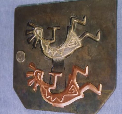
Kokopeli design by me, (one step) cut and embossed in 26 ga. copper :

KOKO011


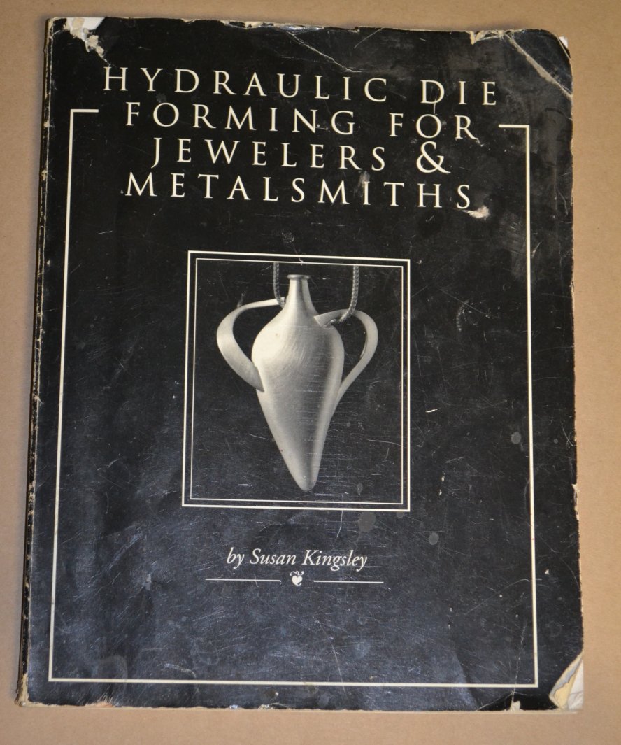
Internal Sun Face – 20 ga. brass and copper :

sunfacebookmark025


Made of tool steel, and heat treated properly, they can cut many thousands (even many tens of thousands, or more) of parts of practically the most intricate shapes (one area of limitations is complex, multi-hole pierced designs) normally cut with a jeweler’s saw. I have been specializing in making these dies since 1987, and have developed my techniques to get the most out of the process in a production environment. I’ve had to encounter everything that could go wrong, and figure out everything to do to make things work right, and find out what is possible or not, what is practical or not.

      Secondly, not all pancake dies are created equal. Some are made in ways that don’t facilitate the cutting of thin or soft metals well (if at all), or are not good for intricate designs, and/or don’t last very long.  In my interaction with die customers over the years, there seems to be more and more people that only have exposure to the not-best dies, and less and less people who understand pancake dies in a fuller, more accurate way. That being in the context of them originally known to jewelers and metal artists as “RT Stamping Dies”, or RT Dies, made in certain ways, capable of certain things. It’s a fairly simple technique, in concept, but the best results require that many things have to be done with precision.

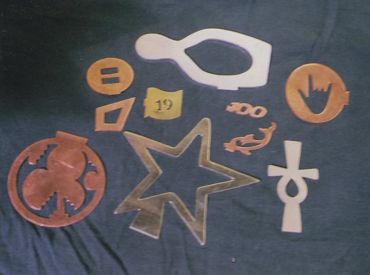
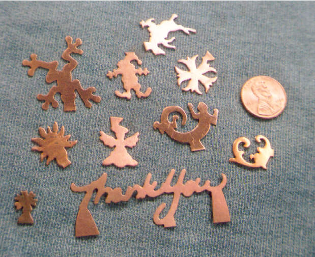
A selection of parts cut with ‘Pancake-Donut’ dies I’ve made for various people:

donuts026


TBHG BF Full Die Set


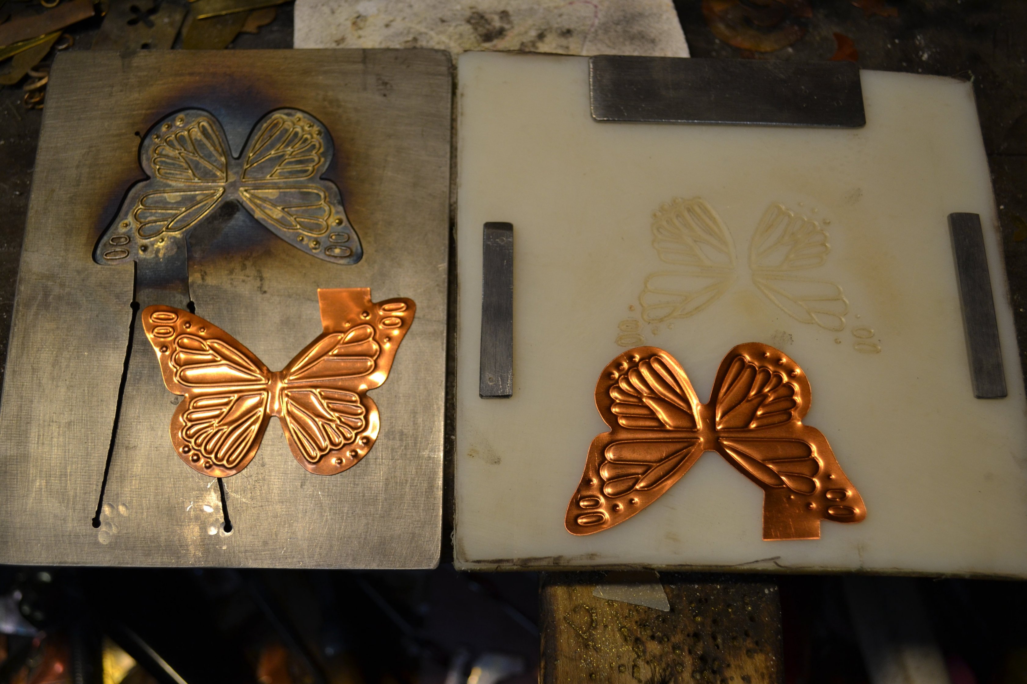
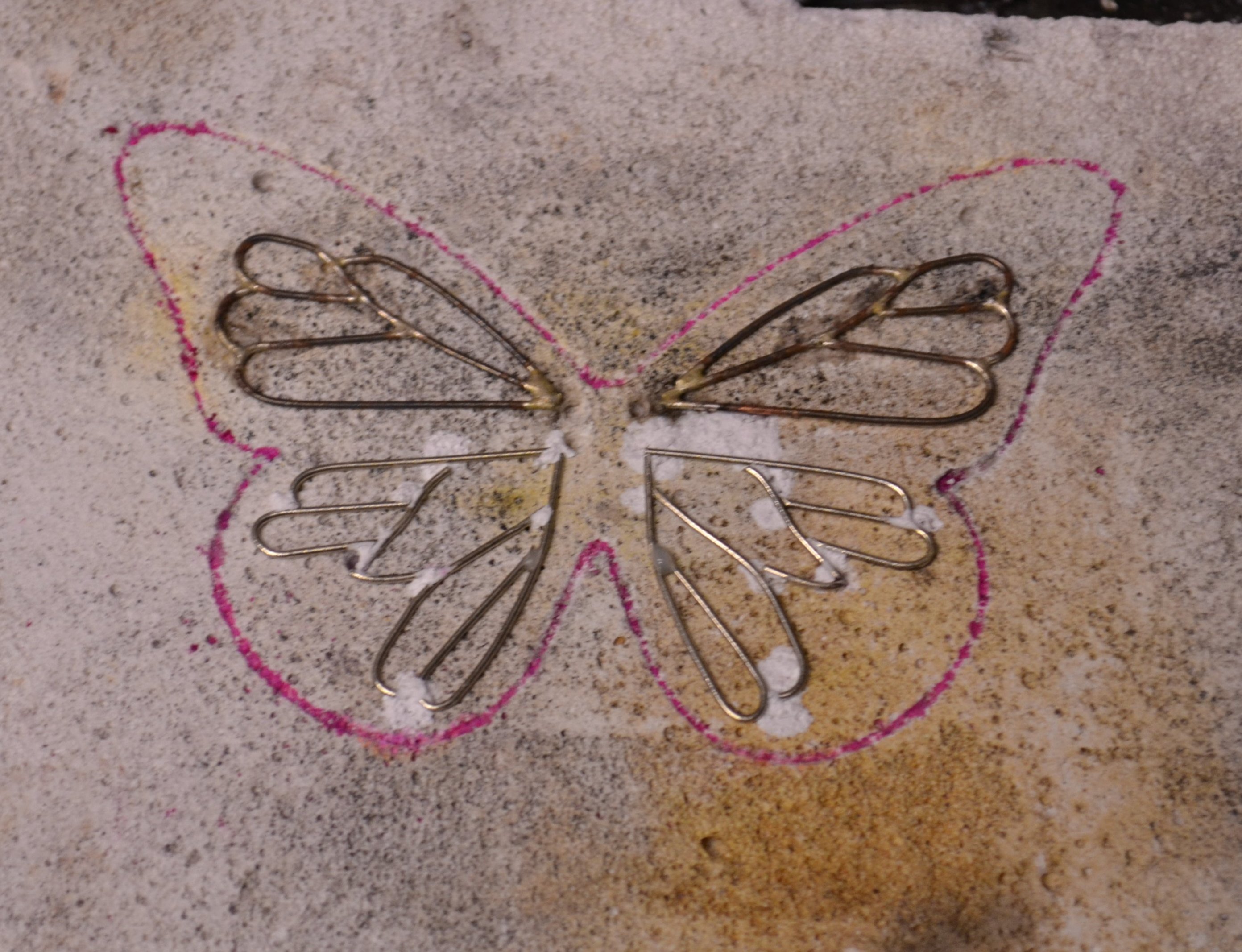
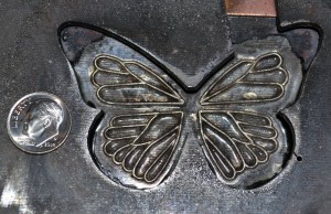
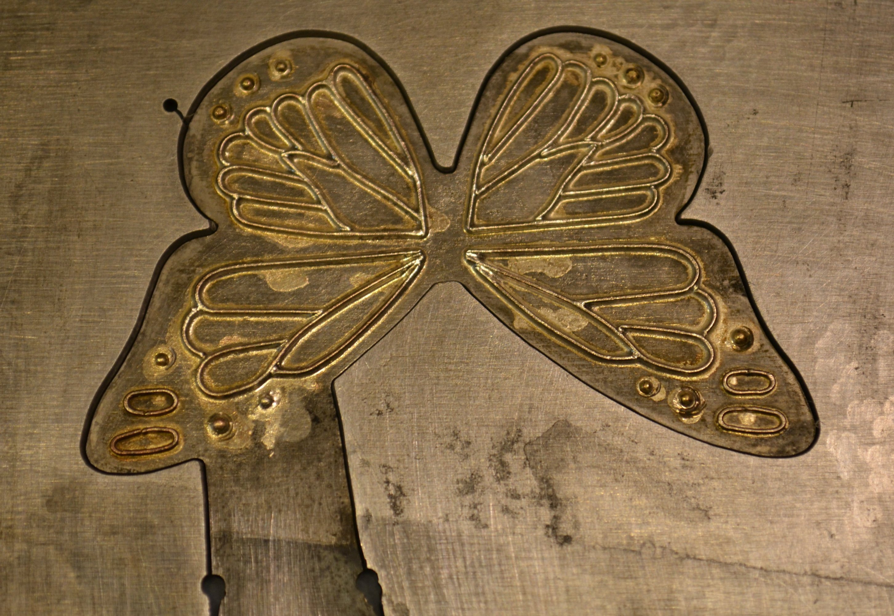
Above:  one-step cut/emboss die and mold . Butterfly design by Timber Bay Home and Garden.

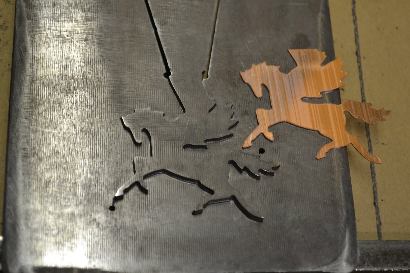
Below: 2″ by 1.5″ Pegasus for 18 ga. copper. 5/64″ steel, #4/0 blade.

Pegasus loaded with part


Pegasus upside of die - back side of part


———————————————————————————————————


The technique of making a blanking die from a single plate of steel, by cutting a flap into the steel, with the design at the end of the flap, has it’s roots in a technique known as The Continental Process. This was developed and used in the early-mid 20th century.

Continental angle diagram


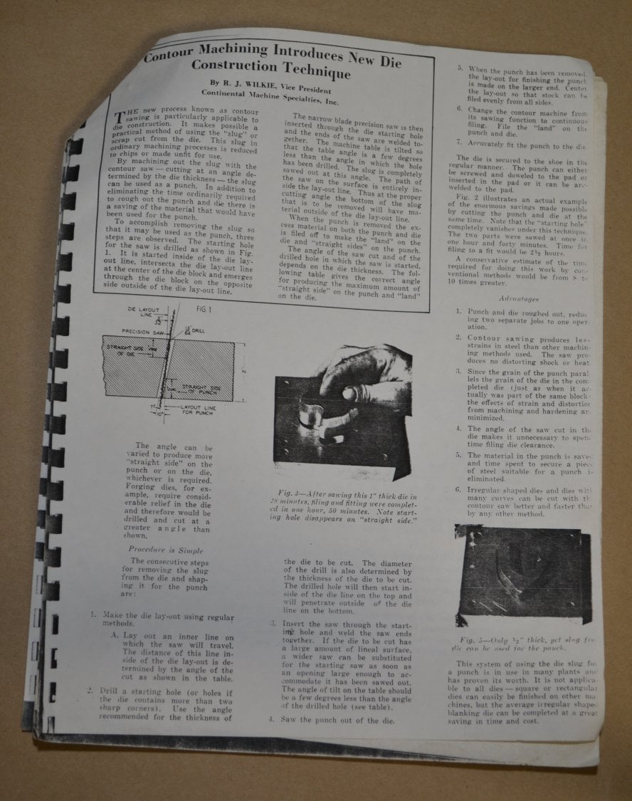
These were still 2-part dies, but without the hinge/flap ,but differ from conventional 2-part die sets in that both male and female parts of the die are created with a single pass of a saw blade through the die stock (plate).That concept was later refined and tweaked, my assumption being that the one-piece, flap/hinge aspect was added then, and presented to the jewelry making community by Roger Taylor of England as The RT Blanking System, and sold in the U.S. by Rio Grande Jewelry Supply. This link  just below is for the original paper that Roger Taylor published in 1980.

https://silversmithblogdotcom.files.wordpress.com/2014/05/project-report-no-12e_1-the-r-t-blanking-system-may-1980.pdf     (copy/paste works on that)

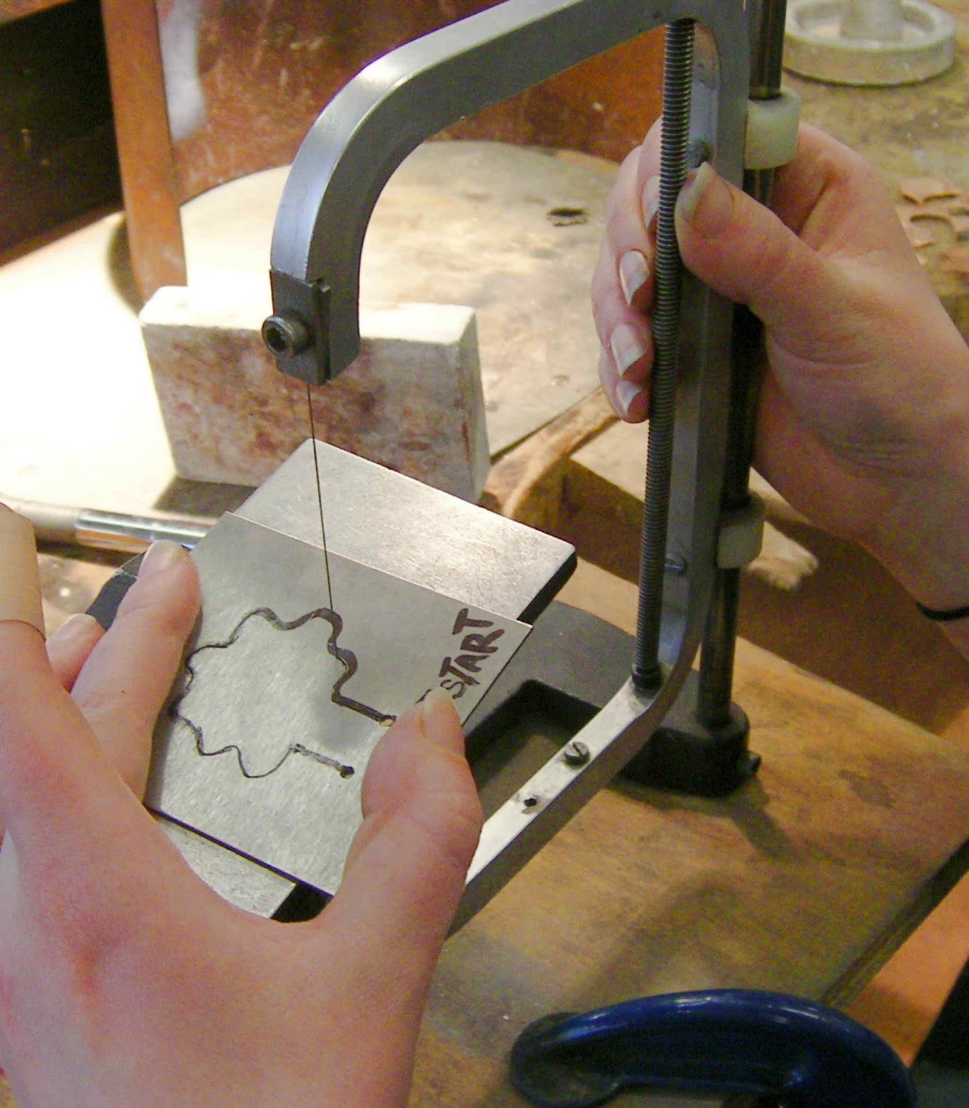
Versions of early R.T. saws :

RT Saw


RT Saw only


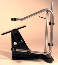
Knew Concepts saw designed by Lee Marshall

KC Guide


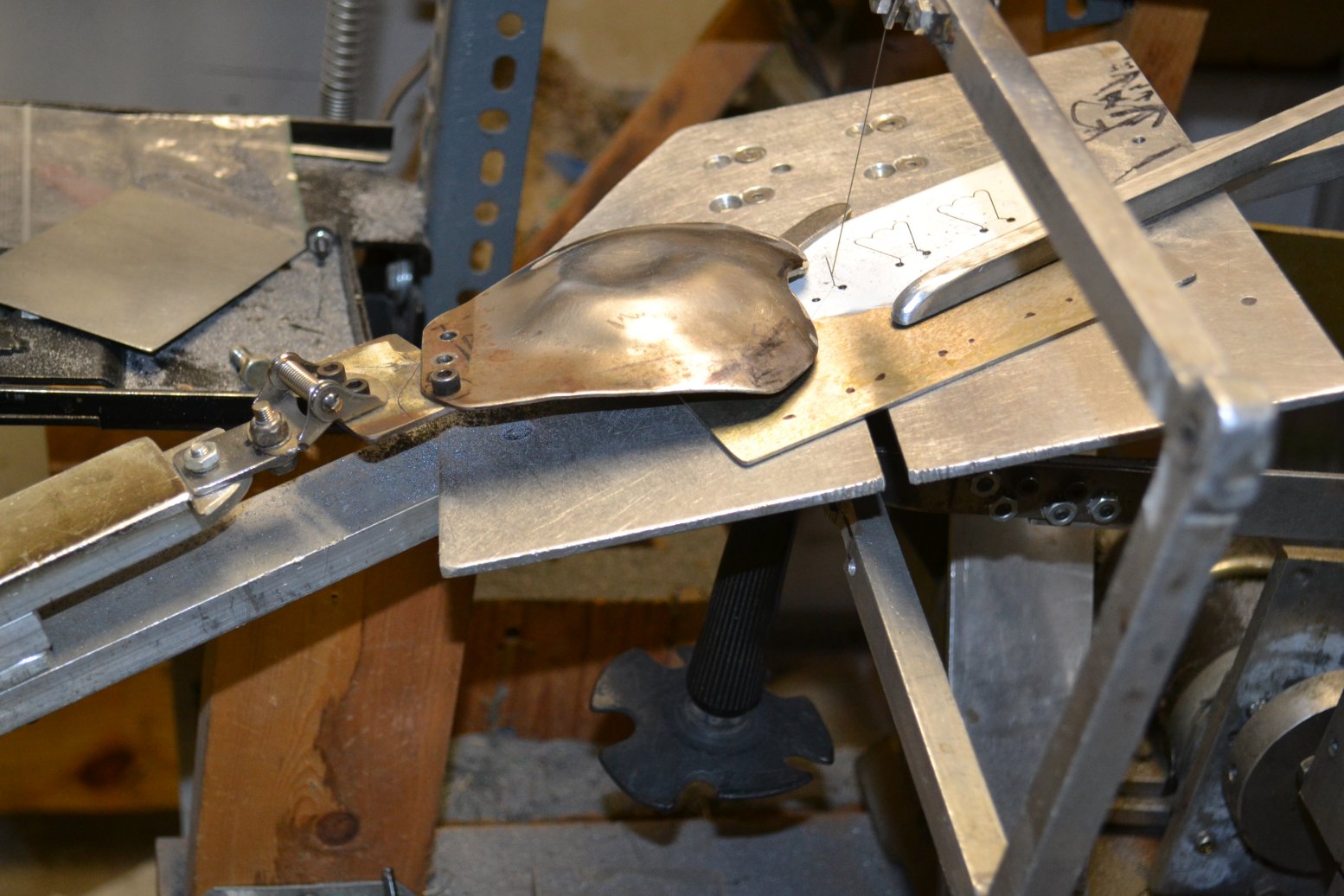
Below:  a saw that I use, which is a modified , motorized version of an original Bonny Doon Saw Guide

motor saw 1


The RT material provides a wonderful introduction to the one-piece die concept and presents some creative ways of utilizing it in the design of pieces. However, it is not a complete instruction guide for start-to-finish hardened dies, and lacks important details. Using that product is how I got started in 1986, and I started Sheltech in 1987, making custom dies and punching out parts for local jewelry manufacturers, in the beginning. Rio Grande also produced a video about the RT Stamping System, which is probably floating around cyberspace, but that was discontinued along with the RT gear  a number of years ago. I’m the person in the video, and I did technical consulting, but have since altered a few of the technique details, so that video in not entirely accurate as far as being a precise “how-to” . That, my friends, is a subject way too long for a short video, trying to cover too much ground at once.


Susan Kingsley’s book ‘Hydraulic Die Forming For Jewelers and Metalsmiths’ (1993 or later version) has a very good chapter, which I consulted on, that covers the basics of how to make your own pancake dies “the right way”. This is highly recommended for anyone interested in making their own dies.

SK book cover


SK diagram


Above: diagram from SK’s book showing basic RT concept of angled cut through the die plate for creating male & female die components that have very tight tolerance, and also the directionality of how to load and press this type of die (the die can be flipped over in the press, with the male part moving downwards, but what’s important to see is which way the male (center) part opens up in relation to the female part (outer ‘sides’ in the diagram). Dies made this way only cut one way; if the die is opened the reverse way , and metal is loaded and pressed, it will  only emboss the shape, not cut the part out.

This book is somewhat  brief, regarding RT/pancake dies, compared to the Taylor paper, but it does cover some important things for making the best dies, such as heat treating, that are not in the RT paper. It shows what was a brilliant tool, the old Bonny Doon Saw Guide, which has been replaced by Knew Concepts saws. The (very nice) Rio Screw press is discontinued, and now hydraulic presses and accessories are offered by Bonny Doon, through Rio Grande, and Potter USA . As soon as I started experimenting with this process, I encountered some significant gaps in the information base that was provided with the RT kit, and this was the genesis of my obsession with refining and perfecting it. That, along with necessity -the mother of invention- which came in the form of a continual stream of people wanting good dies, many of whose projects forced me to push the limits of what had been done with this process.


5″ Sun Face die, my design , shown without it’s solid (plastic steel & Lexan) conforming mold/base. Samples cut in 26 ga. copper .

bth_Sunface4004


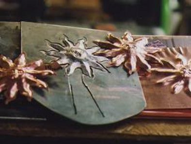
Below: Snowflake design by Paul Crabtree of Colorburst Studios.

The left die is a normal pancake die. The right one is for the set of center holes and is at the extreme limit of what is possible with this process.

SnowflakePiercedDies011


TBHG BF Die and Part


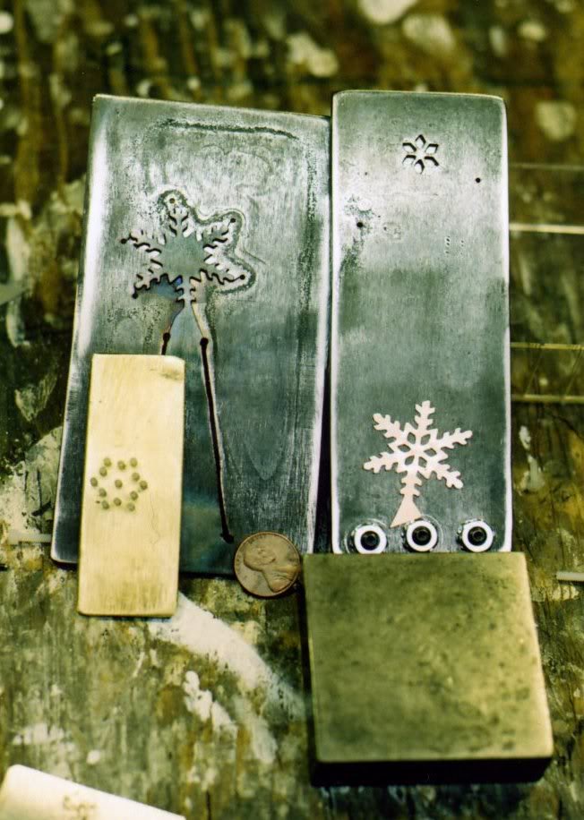
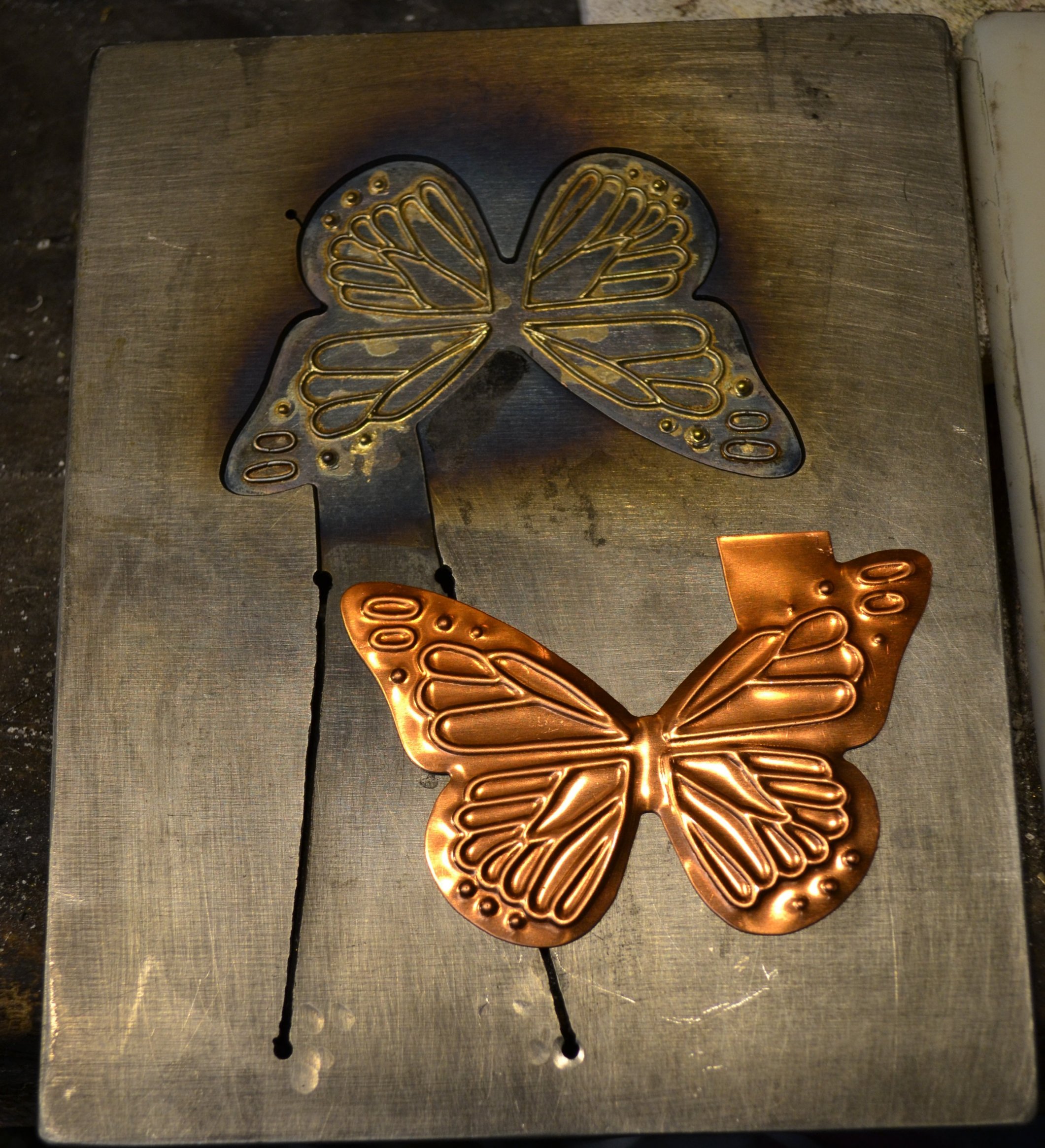
Above: close -up of the (one-step) TBHG butterfly 

They (Lisa M. Fida) have run many, many thousands of these in

soft 30 ga. copper.

—————————————————————————————–

Below: a selection of small, intricate parts cut from normal pancake dies (non-donut)

Stuff, Tiny and Fancy


The most important attribute of these dies is that  when cutting the design (with the saw reciprocating vertically)  the steel plate is tilted at a specific angle so that the tolerance between the male and female components of the die becomes  tight. This happens because the tilt compensates for the width of the gap left by the saw blade. This one aspect is  incredibly important, and at the core of the entire “RT” concept. It’s like a pair of new scissors that’s nice and tight at the joint, cuts very cleanly, and works on thin material, whereas a loose pair will have problems, and may not even cut. That’s because material squeezes in between the scissor halves, because the joint is loose and sloppy, and leaves room for the material to go into. If the tolerance is tight, there’s nowhere for the material to go, except to get cut.

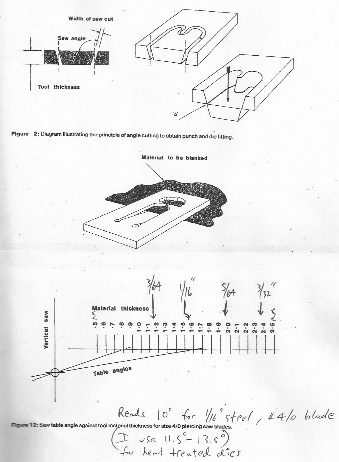
Below: page from the original R.T. paper, showing the basic concept of creating positive and negative die parts with one saw cut , leaving very tight tolerance between them. Noteworthy is my handwritten note about the angle used for a 4/0 blade cutting 1/16″ tool steel. It  shows the difference between the “theory” of what angles to use, and what angles actually work best with heat treated dies.  I do what might be thought of as extreme die making, because my angles can be past the limit of what is advisable for anyone without some experience doing this .

RT Paper - diagram and chart


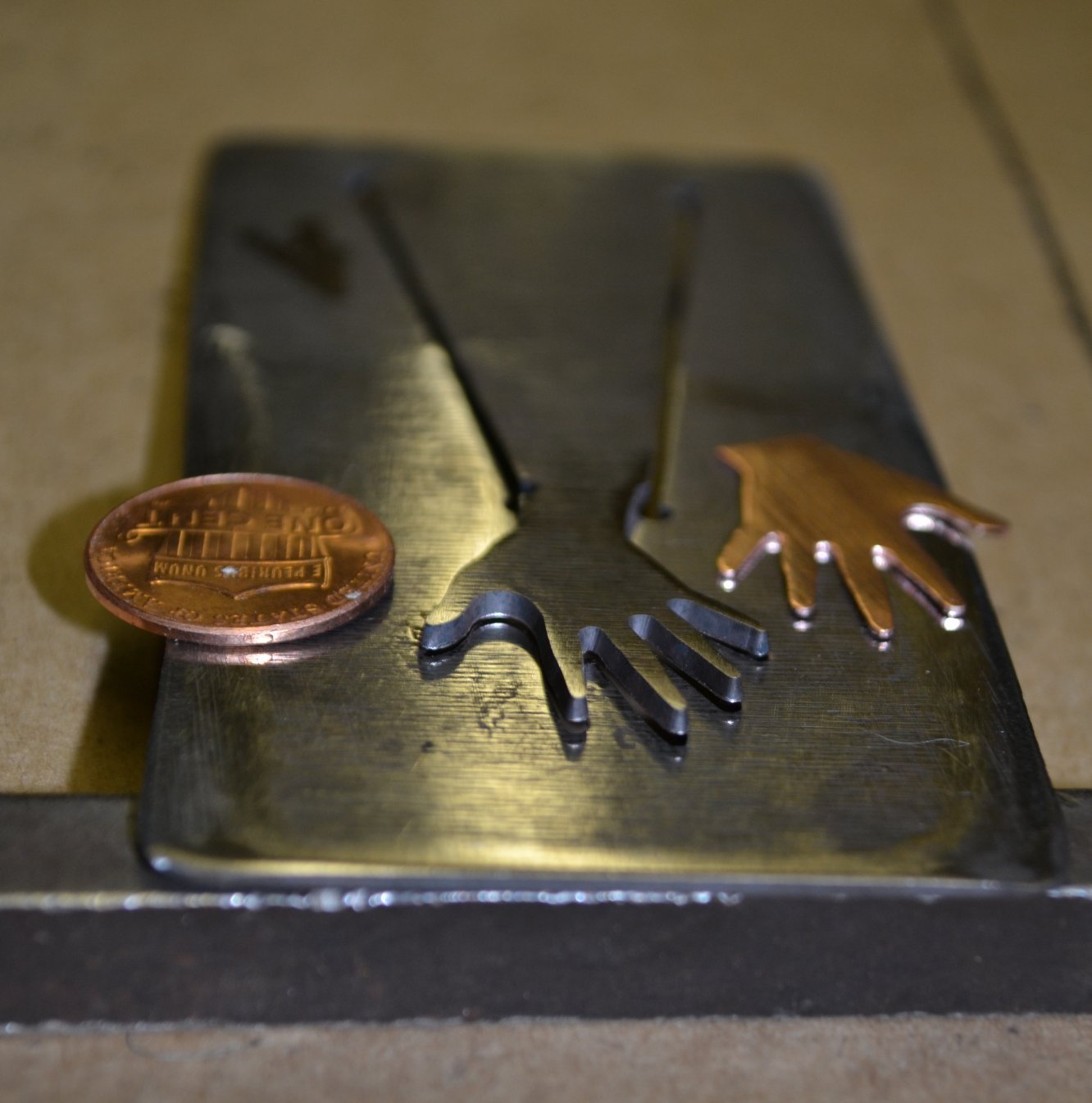
Below: small hand die , of 1/16″ steel, cut with size 4/0 “Platinum” blades. Sample cut in 24 ga. copper

A hand finished open


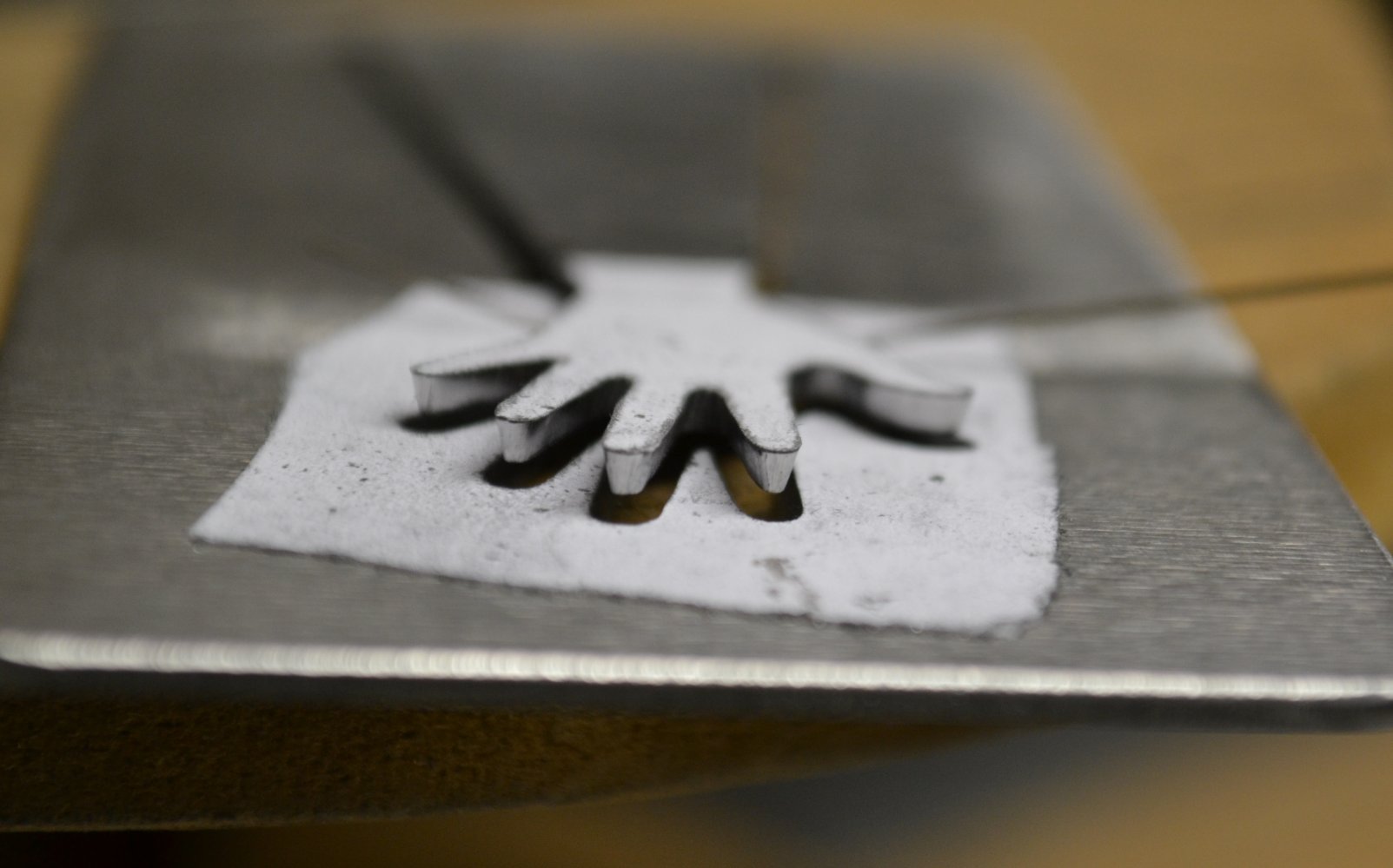
Below : the same die, right after sawing , opened the reverse way to show the tapered cross section of the fingers due to the sawing angle .

A hand open unfinished


The gist of all this is that  any pancake die cut with no tilt  starts out just like loose scissors because the cut that makes the flap is perpendicular to the steel plate. The importance of using the correct angle becomes more obvious when cutting thin or soft metals , and certain alloys and tempers that have more resistance to shearing. It has been my “job” -as well as an honor and privilege- to make and use tools for so many great people over the years . It has also been imperative to get the dies to perform as well as possible  and, if made correctly , they can be incredibly productive. If  not, they can be next to useless in some situations where a well made die would shine.


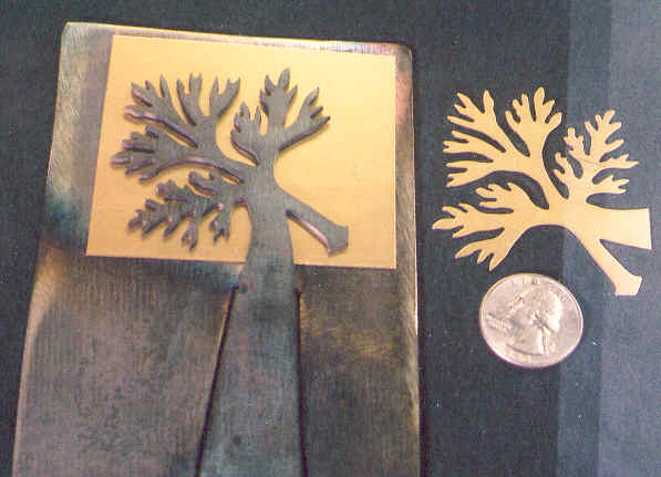
Even when attempting to make pancake dies the correct way, it’s easy to make them just a little bit loose, and have the same sort of problems as described (and encountered by many of you). Well made dies (even heat-treated tool steel ones) can loosen up with extended use, and also start to have problems. So, in my not-actually-humble opinion, it’s (generally) extremely important to start out very close to what is as tight as possible, so that a die can cut parts cleanly for as long as possible, and in many situations, it is essential. What steel is used is also very important. Inexpensive dies are made of inexpensive steel, which is not fully hardenable,  so pointy or delicate areas will fail much sooner that they would on heat treated tool steel die, and many small, complex kinds of designs should not even be attempted unless tool steel is used and properly heat treated. I make almost all of my dies out of 0-1 oil-hardening precision ground flat stock, which has the best overall characteristics for this process. With the right machine, a Wire EDM, pre-hardened flat stock can be used, but those are expensive to buy or get work done on, and not the scope of this piece. For dies bigger than the sizes of pieces used in jewelry (6″ by 8″) for example) it would be better to scale up the thickness (to 3/16″ perhaps) but there are drawbacks to this, such as cost, difficulty of making, and weight. I had one die made to cut and shape a 9″ leaf in 26 ga. copper; the die was 24″ by 12″by 3/16″) and was, needless to say, physically hard to use. The only other “improvements” were/are doing more with the process than just cutting flat parts without holes, which I have developed methods for.


——————————————————————————————

MY    Videos :

Fundamentals of Using Pancake Dies

Pancake-Donut Blanking Dies:

Pancake Die Mutations- One Step Cut and Emboss

Pancake Die Demo 1

Sheltech Show and Tell – Various Parts…

Manual and Motorized Die Saws That I Use


Here’s a nice video put out by Rio Grande, featuring Jayne Redman. The animated cross section of the angled-cut die is especially effective at showing what the two old diagrams above are all about.  Some technical details don’t align perfectly with mine ; the big one would be that, for absolute best results in maintaining a correct sawing angle, you don’t rely on freehand sawing. Hence, the BD saw guides I use, the Knew Concepts saws, and, oh yeah, from the man who started all this, the RT saw. A device which holds the saw/blade in perfect orientation to the tilted saw table. Given that the variations in angle I use to make a specific die a little tighter or looser are about 2 degrees, freehand sawing just doesn’t cut the mustard if you’re operating close to the limit of tightness. I seriously doubt anyone can consistently saw within 2 degrees . This means that one is extremely likely to overshoot and undershoot the perfect angle without a saw-holding device .

Web:
http://sheltech.net/

Email :

sheltech@yahoo.com

darshelton@hotmail.com

Now on FB :
https://www.facebook.com/Sheltech-1186953114672908/
https://www.facebook.com/profile.php?id=100011659549448
 

David “Dar” Shelton – March 2018


{ 8 comments }

sheltech

sheltech

sheltech

Latest posts by sheltech (see all)

The Timber Bay Embossed Butterfly

by sheltech on April 4, 2015

TBHG BF Die and Part  The BF design is by Lisa M. Fida of Timber Bay Home and Garden  http://www.timberbayhg.com/   and I have done several other similar jobs for them . This BF is 3” wide by 2” tall , made from 26 ga. copper. The die works as a one-step cutting and embossing set , where the pancake die has wire designs soldered to it’s face, and a bottom base plate  female mold made of ½” nylon .

To begin, I chose to use 5/64” tool steel for the die , which is two thicknesses (3/64”  would be sufficient to cut a flat BF that size) up from what’s needed for 26 ga.  . This is to give the die more strength and rigidity , and to help it stay as flat as possible (without resorting to using even thicker steel).  So, the first phase was to cut and heat treat the pancake die , then use a piece cut from it as a template/guide to layout the next phase : making the wire designs for embossing the wings.

In all previous similar die projects, the designs were less  complex , and my approach was to fabricate the wires to shape in separate pieces , then arrange them all properly onto the die face while fluxing and heating the whole affair right before soldering . Usually I get everything in place and carefully, gradually flux it up with white paste flux , and heat things slowly so the wires don’t move around much. Sometimes I tin the die face  first , but usually I get things consolidated in place in molten flux , and then apply super-easy wire silver solder .

I procrastinated doing the wire designs for a couple of weeks because I knew it was going to be a difficult job , and when I finally forced myself to tackle it , I took a serious look at the artwork of the wings and literally thought “what have I gotten myself into now !?  “ . Not that I didn’t think I could do it; just that I knew I wasn’t going to make out very well with the price estimate I’d given . After a few minutes of staring at the design with what must have been a dumb look on my face , I came up with a plan .

TBHG BF Pre-Soldering Wire Modules


The pictureat right  is of how that plan looked in action : soldering 4 modules together first . the artwork had the wing designs broken up into four separate sections , so I figured my best (and only good) choice was to build four separate sections together first , and then arrange those on the die face for a much easier soldering of design components to die .  I took the flat piece cut from the die and placed it on a foamed ceramic  board , then traced around it with a red pen, then marked four  corner points to locate each of the four modules . I fabricated the basic wire pieces in the usual manner , then took wires from one module at a time and arranged them on the soldering board , and used medium solder to make the modules. The wire is 24 ga. nickel silver round wire . The pic shows the two top wing-half modules already soldered , and the bottom two in the process of soldering .


—————————————————————————————————–


TBHG BF Soldering Close Up w Dime


The picture with a dime next to the BF shows the die just after soldering the four wire design modules to the die face . The flux is still on and the strip of copper used to prop the die open for soldering is visible. My soldering setup for this is a simple as can be;  I place the butt end of the die in an arbor press which has platens that are heavy enough to function as a clamp, holding the die out horizontally.  I use an oxy-acetylene welding torch for most of these operations, with a reducing  flame . The die is propped open to allow the heat to be concentrated on the design area instead of the outer body of the die.  This is to minimize the possibility for the body of the die to deform, distort , warp, or shift out of alignment. With a relatively simple design shape such as this butterfly , the  BF itself is not likely to change shape at all , but what can happen is that it will warp out of flatness if heated only from the back . Too much such warping could be very bad for  an embossing die like this . It could be very difficult to get the nylon base block to conform correctly to the  die’s curvature .

My approach is to heat mostly from the back slowly to allow the flux to settle down and minimize oxidation of the nickel and steel areas to be soldered . Once the flux is molten and almost ready for soldering , I heat from the top so that the wire solder will melt quickly and not too much more time is spent with the die being hot .  A few minutes at the flow temperature of 56% -silver solder is not enough to take that much of the hardness out of the pancake die , but I am careful not to heat things past where they need to be , or for very long . I do not make my dies very hard compared to conventional die sets , and a die like this doesn’t need to be very hard in order to cut 26 ga. soft copper for a very long time. Once the soldering is complete , I anneal the hinge of the die at the area just below the design (to leave it more flexible) and then the base of the hinge , to leave the die in a semi-open position . A barely-visible  dull red color is a good indicator of heat for positioning the hinge .


The next picture shows the die cleaned up after soldering on the main wires  and the shot after that is of the die with all of the detail designs soldered on , and the die realigned after soldering . The only corrections that were needed were standard hinge-shifting that happens to almost every die when I torch the hinge as already described. A few bangs with a big ballpein hammer is all it takes .


TBHG BF Die Face Close Up


So, on to the next phase : creating the female embossing  mold , but first ,  bit about why such a mold/base is desirable and/or needed in the first place . Basically  it’s to make the embossing happen at lower pressure –therefore faster and easier-  than is possible pressing into either  a urethane pad or a flat nylon (or other soft plastic) block .  I’ve made lots of similar dies  but with less-complicated  embossed designs, and many of those work fine pressing into a hard urethane pad . The detail isn’t as crisp , and it’s not the best thing for dies to press them into anything that gives like urethane does under pressure . I have cracked dies  with this method, and one should never , ever use urethane with pancake die that’s meant for cutting flat parts . Some of these cut-and-emboss dies push down into the urethane so much that it prevents the die from closing all the way , which means that the part doesn’t get cut all the way out.  Some designs take more pressure than is practical , or available , to fully emboss , so even though it’s a lot more work to make the conforming mold, it’s often necessary, and definitely worth it , because of results  and time save in production . This particular BF might form well pressing in hard urethane at 40 or 50 tons, but with it’s solid nylon base , with the negative designs melted in, it only takes about 15 tons .

One option for melting the design into the nylon block would’ve been to heat the die and press the naked die down onto the nylon , but this would only create grooves exactly the width of the wires on the die . The ideal size of the grooves is actually the wire diameter ,  plus the thickness of the target metal being embossed . Also , since the target metal will never actually be conforming 100% all the way tightly around the wires –at least not with 50 tons or less-  it’s best to create a mold cavity that allows for the lack of complete forming . The obvious solution to all of this is to take a piece of the target (26 ga.  Cu) metal and form it against the die a couple of times  , to get good, crisp detail, and use that piece to heat and melt the nylon block with .

Since the soft 26 ga. formed piece was too flimsy to heat and press into the base by itself, I decided to try something new . After putting steel locating strips on the nylon base – for keeping the die in exact  position for this process and during production runs-  I placed the formed piece back in the die , then placed the die onto the nylon block, then heated the die itself , and then pressed  it so that the perfect size and shape  of grooved were melted into the block . This was a very delicate process  because of the way nylon boils and then burns if  it gets too hot . I didn’t want the die to get too hot either  and I’m guessing this worked nicely at around 700 F , possibly a bit more, but definitely under the temperature that would’ve caused the die to glow at all . I only pressed this arrangement in my one ton arbor press , and I felt very fortunate to have gotten the heat and pressure  right , since the nylon neither boiled nor burned , and didn’t flow excessively . Cleaning up solidified nylon after excessive unwanted flow in detailed areas  like this butterfly can be tricky and very time  consuming . I got off with a little bit of levelling with a file . I believe I stumbled onto a perfect heat,   pressure ,  and design  combination that caused the nylon to deform without too much melting, and no burning  . Some previous nylon-melting adventures have been rather messy, and the fumes from nylon smoke are very toxic !

———————————————————

The next picture is of the entire die set , with a couple of parts , showing the  obverse and reverse faces. The nylon block is ½” thick , and is a good thickness for this project . Thicker is not necessary,  and thinner would not be thick enough to guarantee rigidity (no warping) over  time . I use the white nylon instead of the black, Molybdenum-impregnated nylon because of how it melts ; the black stuff boils more easily  , which interferes with clean, smooth molding/melting . I chose nylon itself because of it’s hardness and durability over some other plastics , along with it’s melting properties .

TBHG BF Full Die Set


The locating plates/strips on the nylon base are made from leftover  scraps  of tool steel  of the same thickness as the pancake die. They should be as thick as possible, to better hold the die in position , without being thicker than the die , so the die can completely close , ensuring proper embossing. I chose this melted-plastic-block  type of mold base  over casting the mold area in plastic steel , and then building that into a mold base, because this type is easier to make  and lasts longer . Nylon has a bit of spring to it in these embossing situations , which gives it more resistance to wear due to abrasion, as would happen more quickly with plastic steel . It’s also cheaper to go find remnants at the local plastic supply warehouse , as plastic steel is on the pricey side.

To locate the locating strips, I used deep-throated vise grips to hold the die to the base, then needle-nosed vise grips to hold the strips to the base, tight against the die . Then I drilled holes for steel alignment pins that position the strips from the front side. Next, I countersunk screws into the underside of the base, and threaded  other , new sets of holes in the alignment  strips , and added a bit of anaerobic thread-lock glue to really get those strips down tight. With this type of die set, keeping the die lined up perfectly every pressing is an absolute necessity , as any misalignment not only leaves an ill-formed part, but will also damage the nylon mold’s grooves .

That’s about it, except maybe a few (more !) technical notes . The pancake die (again) is made from 5/64” 0-1 tool steel; I sawed the butterfly section using size 1 Pike Platinum blades , with the table angle set to about 13.25 degrees . This leaves the die very tight , which it needs to be for soft 26 ga. Cu . I did the standard oil quench from 1500 F , then tempered the die at around 800F , which left it soft enough to never worry about breaking .

A project like this could certainly be done as a two stage operation , with a plain pancake die and a wire embossing die used all by itself , without the matching female mold , but as explained, a design this detailed  , with this amount of forming needed , would take well over 20 tons , and would lack in sharpness and/or depth , unless close to 50 tons was used .

I’ve made other very similar setups using Lexan (polycarbonate) as the base material . Instead of melting the designs in, I first used the wire-decorated die to press into the Lexan block with 50 tons. This by itself leaves grooves that can only be as deep as the wires themselves (not as deep as the wires plus the copper thickness, as is ideal, and as was previously explained). So, in these cases , I either left things as they were and accepted the results, or used a round bur on a flexshaft to carve the grooves more deeply . This is hard to do neatly , and for me , melting into nylon makes for much cleaner- looking parts. The two projects that recently pushed the evolution were both such cut-and-emboss dies with Lexan bases . One was a small Scotty dog, where the fur lines were made from 26 ga piano wire , and the parts were made of 26 ga, nickel silver  . I knew I needed a solid plastic mold , not urethane , and I knew I needed the mold to have the matching female grooves in it, and not just a bare , flat Lexan base (an approach  which actually works very well for smaller items that don’t have extremely detailed or extensive embossing being done). I used the finished Scotty die to press lines into the Lexan base with 50 tons , and then made a piece and pressed that with the die , into the base at 50 tons again, to deepen the grooves.  The other such project was a 4” Ivy leaf with lots of veins made from 18 ga steel wire.  The kicker with this Ivy was that it needed to cut and emboss 20 ga. copper , so I knew I absolutely had to have a solid plastic mold base with the matching grooves . Same tactics as the Scotty , with lots of subsequent carving out with burs . That one ended up working well at about 15-20 tons .

The culmination is , of course, the Timber Bay butterfly ,  calling on all previous experience and experiment , and refining techniques  to one more level .

Dar Shelton   4/3/2015


{ 1 comment }

sheltech

sheltech

sheltech

Latest posts by sheltech (see all)

Amazonite and Silver Set

August 8, 2014

  These pieces came out of a basic idea of  the ‘S’ shape , and I started with the rings, using  half-round wire , forging and bending the ends .  The rings and bezel cups were rough-polished  before soldering .  Next came the bracelet , slightly more ambitious , with the same concept of one […]

Read the full article →

(Hemi)Spherical Icosidodecahedron , Con Chihuahuas

January 16, 2014

This is a scale model for an eventual large yard sculpture , planned to be somewhere around 14 feet in diameter by 7 feet tall , made from electrical conduit (for the framework), round steel rods, and galvanized steel sheet . The model is powder coated  (blue) stainless steel , plain stainless steel, and galvanized steel sheet, […]

Read the full article →

One-Step Cut/Emboss Stag Design

January 15, 2014

                              This is a one-piece die that cuts and embosses in one pressing . The copper sample is 26ga. (.016″) ; the embossing wires are 24 ga. nickel silver (round) , super-easy-silver-soldered to the face of the die. When pressing, the […]

Read the full article →

Mini-Spoons For Solje Pin

August 19, 2012
Read the full article →

Drilling Jig

February 7, 2011

this is a specialized drilling jig for drilling 1.15mm holes in the center of a stack of 8mm circles . the vise grips have been modified by drilling clearance holes in both jaws. also, a bushing plate has been soldered to the upper jaw ; this plate fits exactly into the space in the aluminum […]

Read the full article →

Jigs and Dies

February 7, 2011

bezel forming jigs for 22 ga., 1/4″ tall copper bezels . the bezels are intended to fit on top of parts cut from existing blanking dies . I made a separate die to cut parts slightly smaller than the existing parts, and soldered a stck of them together , about 3/8″ tall . these are […]

Read the full article →

Merkabah Sculpture Photos

November 4, 2010

  left click to enlarge !!!left click to enlarge not all pipes and rods are coming from the top point; this view lines up two hubs left click to enlarge I will let these photos speak for themselves. Tech details are in previous posts. Dar Shelton

Read the full article →

The Big One (no jewelry content)

October 11, 2010

Two Tetrahedra , 14 feet tall, made from welded electrical conduit (and thicker 1″ pipe for legs). Ignore the legs and you have two tetrahedra (one pointing up and one pointing down, almost lined up in this view so that you see the 3-D tetras as a 2-D star of David ) . There is […]

Read the full article →

WordPress Admin